|
|
楼主 |
发表于 2016-1-12 11:37:22
|
显示全部楼层
|
Comparison
Now I am comparing TS100 with a traditionalmodel. The objective of the comparison, however, is not to judge which one isbetter. After all, prices vary from models. And satisfaction varies from habits.The comparison here chiefly serves to give a more detailed picture of TS100’shighlights.

Forstarters, let’s look at both handles. The FX-600 in my hand regulatestemperature through a knob. Its adjustable range is between 200°C to 500°C. Its cap temperature is relatively high ascompared to 400°C of TS100°C. But it does not display temperature. Thetemperature regulation extent is 50°C, not so precise as compared to that of TS100.Its working condition can only be judged by a blue LED light.

Interms of the connection between the handle and the power cable, FX-600 isintegrated with the power cable. It works with direct connection to a 220Vpower supply. In contrast, TS100 works on a DC power and its power adaptor isremovable. So TS100 is more portable.

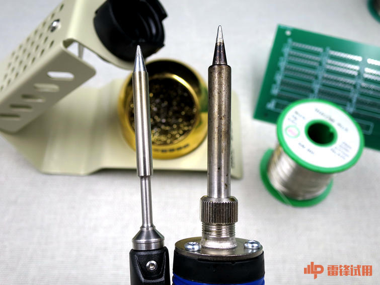
Bothheating elements are of the same materials. FX-600 looks distinctly thicker.Its low-temperature reserve area is not so large as that of TS100. However,during operation, I found FX-600’s range of melted solder at the tip is relativelylarge as compared to that of TS100.

Thereis a difference between the interfaces of both heating plates. For TS100 theconnection is inseparable, while for FX-600, disconnecting the external metalfrom the internal heating plate is available by loosening the screw cap. Moredetails can be found from the following pictures. In other words, FX-600 allowsan easier replacement of the external plate (some users like pointed cant metaltip).

Asfor the feeling of touch and the means of holding, they vary from individualhabit. I am used to a relatively thick handle. So I do feel uncomfortable withholding TS100 that has a thinner handle. In terms of flexibility, however,TS100 is way better, especially for soldering blind spots on some circuitboards or micro-electronic components and parts.

Incomparison of the control circuit board, TS100’s looks obviously more organizedand advanced. On the circuit board of FX-600, there are even a couple ofexposed wires. Nonetheless, both soldering irons work on similar principles oftemperature control. From here it can be seen how the heating plate differsfrom the external metal as I mentioned above.
Soldering
Following the introduction to details ofappearance and ways of operation, official trial begins. With some of myelectronic components and parts at hand soldered on the PCB, I will give you adetailed picture of the shapes and forms of the soldered points, the meltingsituation on the solder plate, and the easy operation of the soldering iron.

Asoldering iron is generally held by the right hand at a 45-degree angle. Holdthe solder wires by left hand and warm up the solder plate. Then contact thetip with the solder wires. When the solder on the pin of the electroniccomponents/parts become shaped like a triangular pyramid, swiftly remove thesoldering iron in case long-time contact leads to damage of the solder plate.

Theway of operating a soldering iron varies from person to person. I think, aslong as you can minimize the risk of a scald and can do a good soldering inwhich the soldered point is pretty and strong, there is no need to do it on standardcodes. In my case, I need to solder a great number of circuit boards every day.Sometimes for the sake of efficiency, I prefer taking a shortcut.


Theblue tool in the picture is a desoldering gun used for removal of solder from acircuit board. First, melt a little bit of solder at the tip of the solderingiron. Then melt the soldered point in need of removal. At the same time,desolder it. Please be careful. During operation of the soldering iron, DO NOT place a piece of cotton textile beneaththe PCB like I did. I did so only for the purpose of a photograph. A standardrule is to place a metal plate or a glass board beneath it to avoid thesplashing of the melted solder. And it is advisable to use a smoke-removaldevice because the smoke produced from the melting of solder will do great harmto a human body.

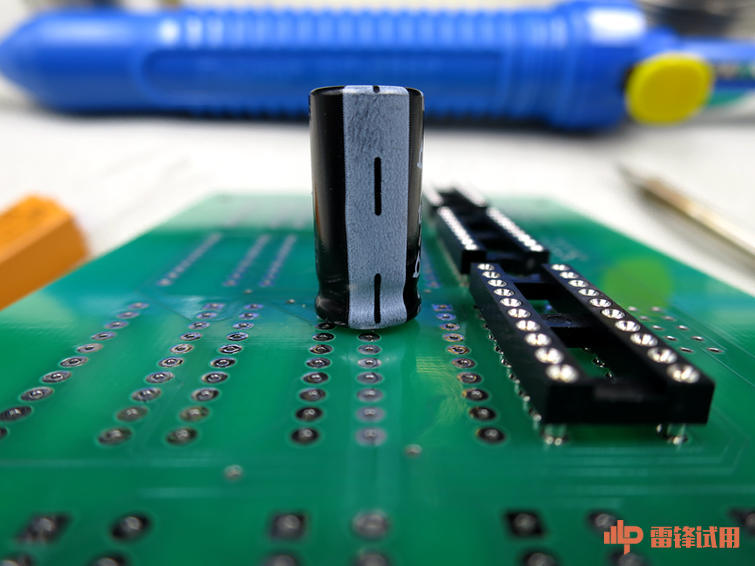
Whenthe soldering is done, turn over the circuit board and it can be seen that thecapacitor and the base board surface is in good contact. There isn’t a serious gap.It is not uncommon that the electronic components/parts with pins such asresistors and capacitors will slip off during the soldering process, contributingto a large gap between the components/parts and the base board. To avoid theproblem above, my advice is, use one hand to support the components/parts andstick a little solder to the tip, then slightly solder one of the pins for thepurpose of stronger connection.


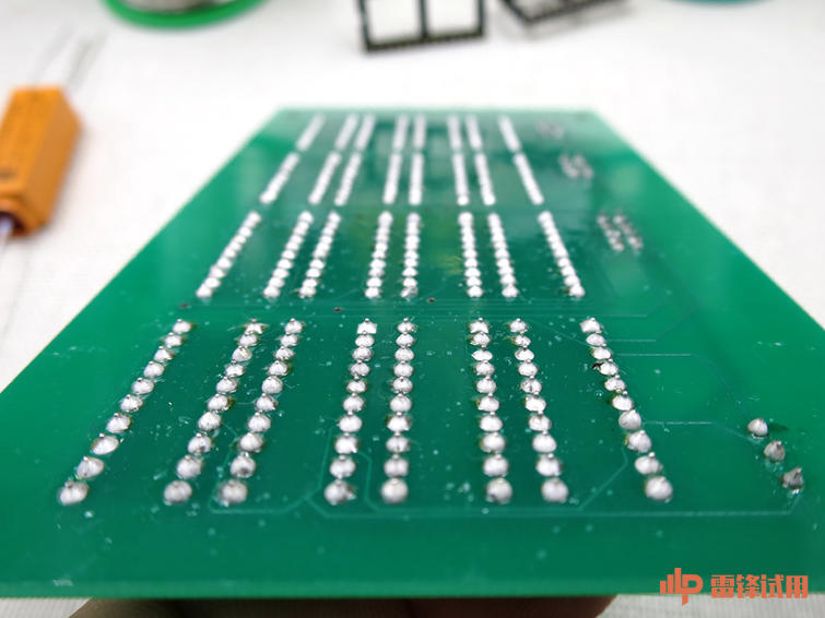
Justover half an hour, I have soldered more than 300 points. This picture shows akind of relay base. The need of the thickness of solder wires is subject toparticular operation. When the distance between the soldered points is closeand the components/parts are relatively small, you need a thin solder wire. Onthe other hand, if the soldered points are relatively large and there is alarger demand of the quantity of melted solder, you need a thick solder wire.As can be seen from the soldered points when the soldering work is done, theymight not be perfect, but the quantity and the shape of melted solder betweensoldered points are desirable. There is neither a leak of solder nor a lack ofit. For over half and hour, TS100 has done a great job. It kept a steadytemperature. Even during the standby time, the oxidation of the tip was not soserious.


|
|